Disclaimer: We support our readers with industry knowledge & research. You support us through our carefully chosen products with links that may earn us a commission.
This type of welding requires approximately twice the heat as the steel of similar thickness. Copper is very thermally conductive. A tip that is one to two times larger than the steel tip is recommended in order to offset heat loss.
Additional heating is recommended when welding large sections with heavy thicknesses. This produces a less porous weld.
Copper can be welded with a slightly oxidizing flame. The oxide that is formed by the flame protects the molten copper.
The flame should not contain any flux to protect the molten copper. For gas welding assemblies, it is better to use oxygen-free copper (deoxidized Copper rod) than oxygen-bearing. The rod should have the same composition as its base metal.
When welding copper sheets, heat is radiated so quickly from the welding zone that it is difficult for the temperature to reach the fusion point.
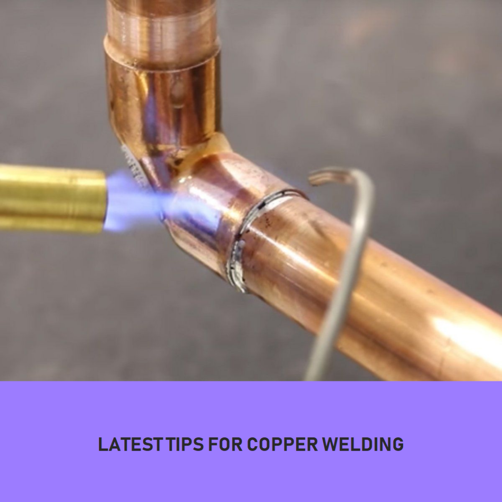
It is common to increase the temperature of the sheet by 6.0 to 12.0 inches. (152.4 to 308.8 mm) from the weld. Start the weld at a point that is not near the end of your joint, and then weld back to it with filler metal. The weld should then be re-started from the beginning point and done in the opposite direction of the seam.
The torch should be held at a 60-degree angle to the base metal during the operation.
To prevent uneven penetration, it is recommended to support the seam on the underside of the unit with carbon blocks or thin sheet steel. To allow complete fusion at the base of the joint, these materials should be channeled.
To prevent heat radiation into the atmosphere, cover the metal at each end of the weld. This would allow the weld’s molten metal to cool down slowly and solidify. Tip – 100% Helium and Gas will Provide the Heat Levels Required to Weld Copper.
Table: Copper Welding Parameters for TIG, MIG, and MMA Processes
| Welding Method | Metal Thickness (mm) | Electrode Diameter (mm) | Temperature (°C) | Welding Current (A) | Gas Flow (l/min) | Travel Speed (mm/min) |
|---|---|---|---|---|---|---|
| TIG | 1-3 | 1.6-2.4 | 650-850 | 60-150 | 8-12 | 50-150 |
| MIG | 0.8-5 | 0.8-1.2 | 600-800 | 100-250 | 12-18 | 50-200 |
| MMA | 1-6 | 2.5-4.0 | 650-850 | 60-120 | – | 50-100 |
Overview
The heat from welding copper sheets is radiated so quickly that it is hard to raise the temperature to the melting point. It is common to increase the temperature of the sheet by 6.0 to 12.0 inches. 152.4 to 304.8mm from the weld.
Start the weld at the opposite end of the joint, and then add filler metal to the ends. The weld should then be reversed from the original point. The torch should be held at a 60-degree angle to the base metal during the operation.
To prevent uneven penetration, it is recommended to support the seam on the underside of the joint with carbon blocks or thin sheets of metal.
To allow complete fusion, these materials should be channeled and undercut. To prevent heat radiation into the atmosphere, the metal should be covered on either side of the weld.
This would allow the molten weld metal to cool down slowly and solidify. Tip – 100% Helium and Gas will Provide the Heat Levels Required to Weld Copper. Copper welding preparation using helium gas torch with filler.
Copper Welding Speed
It is important to have uniform welding speeds. The filler rod’s end should always be in the molten pool. The outer flame envelope must be used to protect the molten metal during the whole welding process.
If the metal does not flow freely during the operation the rod should be raised. The base metal should then be heated to a red temperature along the seam. Continue the weld until you have completed the seam.
Welding thin sheets
For welding thin sheets, forehand welding is preferable. For thicknesses greater than 1/4 in, the backhand method is preferable. (6.4 mm) and more.
Sheets up to 1/8 inch. A plain butt joint with squared edges (3.2 mm thick) is recommended.
Thicknesses exceeding 1/8 inch should be considered. For thicknesses greater than 1/8 in (3.2 mm), the edges should be rounded for an included angle between 60 and 90 degrees.
This will allow for penetration and spread fusion across a large area. Brazing operations can be performed with butt, lap, and scarf joints.
Clearances that allow the penetration of filler metal should not exceed 0.002 to 0.03 in, except for large diameter pipe joints. (0.051 to 0.076 mm).
Large-diameter pipe joints can have clearances between 0.008 and 0.100 inches. (0.203 to 2.540 mm). You can either use inserts of filler metal to make the joint or you may feed the filler metal from the outside once the joint is at the right temperature.
The scarf joint is used to join bandsaws or joints where double thickness is not required.
Copper Nickel Alloy Welding
Wherever high purity, resistance against bacteria, and biofouling are needed, copper-nickel alloys can be used. They have excellent strength and formability. If you follow the correct procedures and take precautions, welding is easy.
There are two main types of copper-nickel alloys: 90/10 copper to nickel, and 70/30 (70% and 30% respectively). These are also known as solution alloys.
This means that any amount of copper can be dissolved in nickel, and any amount of nickel can be dissolved in copper.
Copper-nickel alloys are not subject to preheat or post-weld heat treatment. The heat of welding does not harden the weld and heat-affected zones.
